Aug 11, 2026Application Notes
Air Velocity Monitoring for Industrial Ventilation Systems
How air-velocity measurements support ventilation assessment and control, including placement, duct conditions, integration and verification.
Direct answer
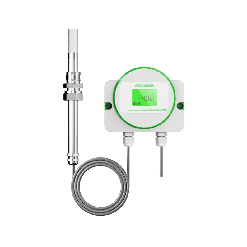
An air-velocity instrument measures airflow speed at its sensing location. The reading can support ventilation monitoring, control or diagnostics when the point is representative and the instrument is suitable for the expected velocity, temperature, humidity, contamination and installation. One point measurement does not automatically represent total duct or room airflow.
Define the measurement objective
Clarify whether the application needs local velocity, duct-flow indication, filter or fan assessment, room-air movement, clean-area monitoring or a control signal. Define the required range, response, output and how the value will be used.
If volume flow is required, the calculation also needs a representative average velocity and the effective area. Flow profile and duct geometry should be considered.
Select the measurement location
Bends, dampers, fans, filters, transitions, grilles and obstructions can create nonuniform or rotating flow. Select a location with suitable upstream and downstream conditions when possible, or use a traverse/multiple points if one point cannot represent the profile.
For room measurements, placement should reflect the intended zone and avoid unintended local drafts unless they are the target.
Review the sensing principle and conditions
Air-velocity technologies respond differently to low velocity, direction, temperature, humidity, dust and contamination. Confirm the selected model’s range, orientation and environmental limits.
Temperature compensation or a low-velocity design does not remove installation effects. Verify performance under the conditions stated in the model documentation.
Mechanical installation
Confirm probe insertion, orientation, mounting hardware, sealing, cable routing and access. Avoid damaging the sensing element during installation and cleaning.
Mark the intended flow direction where relevant. For adjustable insertion, document the final depth and position so the measurement can be reproduced after service.
Electrical and control integration
Verify supply, output, scaling, units and control-system input. Define filtering, alarm limits and failure behavior. Excessive filtering can hide real changes, while insufficient filtering may make a turbulent signal difficult to use.
For fan or damper control, test the loop response and define safe operating limits. A sensor should not be the only protection where regulations or equipment design require independent safeguards.
Commissioning and verification
Check model, range, mounting, orientation, wiring and scaling. Compare the installed reading with an appropriate reference or traverse when required by the application.
Record the duct or room conditions, fan/damper state and baseline. Later comparisons should use similar operating conditions.
Maintenance
Dust, oil, fibers and condensation can affect the sensing element. Inspect and clean according to model instructions. Establish verification intervals based on contamination and process importance.
A stable signal does not prove the sensor is clean or correctly positioned. Check the physical installation when the process or ventilation system changes.
Practical questions
Can one probe measure total duct flow?
Only when the point is shown to represent the required average or an approved method provides the relationship. Nonuniform profiles may require multiple points or a traverse.
Is a low-velocity sensor automatically suitable for cleanrooms?
No. Range is one factor. Placement, contamination, response, output, calibration and applicable cleanroom procedures must also be reviewed.
Does airflow monitoring guarantee indoor air quality?
No. Air quality also depends on contaminants, filtration, outdoor air, distribution, occupancy and operating procedures.
How should alarm limits be chosen?
Use the ventilation design, equipment requirements or applicable site criteria. Do not copy limits from an unrelated system.
Next step
Provide the duct/room layout, expected velocity, temperature, humidity, contamination, output and control objective. HRT can review available air-velocity configurations and installation questions.
Application review checklist
- Expected velocity range, flow direction and duct or room geometry.
- Process temperature, humidity, contamination and access for cleaning.
- Mounting position, output, power supply and control-system interface.
Contact our technical team with the operating conditions, installation details and required interface to request an application and configuration review.