Aug 13, 2026Technical Guides
Measurement Selection for Precision Process Environments in Taiwan
A practical guide to selecting pressure, level, temperature, humidity and viscosity instruments for tightly controlled industrial processes and demanding installation conditions.

Direct answer
Measurement instruments for precision process environments should be selected from the actual process conditions, required uncertainty, installation geometry, material compatibility, output requirements and maintenance plan. A location or industry label alone cannot establish suitability. For projects in Taiwan, the same engineering discipline applies: define each measurement point, verify the exact model and configuration, and retain a clear record of assumptions and unresolved conditions.
Define the control objective
Begin by identifying how the measurement will be used. A value intended for local indication has different requirements from one used for alarm, batch control, equipment protection or closed-loop control. Document the normal operating range, expected excursions, required response, allowable uncertainty and the consequence of an incorrect or unavailable reading.
The control objective should determine the instrument requirement—not the most prominent number in a product description. A nominal accuracy value does not by itself describe stability, installation effects, temperature influence, calibration practice or total measurement uncertainty.
Review the complete operating conditions
For every measurement point, collect:
- measured medium and expected composition;
- normal, minimum and maximum values;
- process and ambient temperature ranges;
- static, dynamic, surge or vacuum conditions;
- wetted-material and sealing compatibility;
- vessel, pipe, duct or room geometry;
- condensation, washdown, dust, vibration or outdoor exposure;
- process connection and available installation space;
- required output, power supply and control-system interface;
- inspection, calibration and replacement access;
- applicable site standards and certification requirements.
Conditions should be recorded separately. Terms such as “clean,” “corrosive,” “high precision” or “harsh” are not complete specifications.
Select technology by measurement task
Pressure measurement
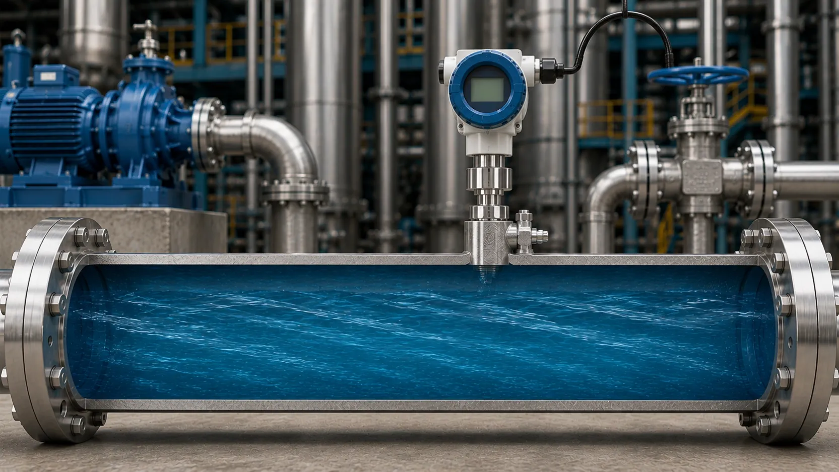
Confirm pressure type, range, process connection, diaphragm or wetted materials, electrical output and installation orientation. Small-range and differential measurements require particular attention to impulse lines, mounting position, temperature changes and pressure transients. High-temperature, hygienic or clogging applications may require a dedicated connection or isolation arrangement.
Level measurement
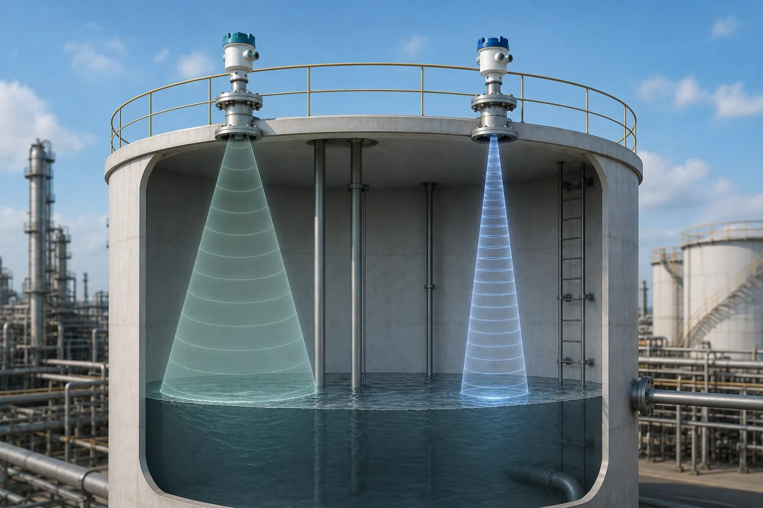
Radar, hydrostatic and capacitance technologies respond differently to vessel internals, foam, vapor, density change, dielectric properties, obstructions and available mounting points. An 80 GHz radar instrument may support focused measurement in some vessels, but the antenna, measuring range, dead zone, process connection and signal conditions must be checked for the selected model and installation. A hydrostatic transmitter also requires review of liquid density, venting, cable routing and mounting depth.
Temperature and humidity monitoring
Environmental monitoring depends on sensor placement as well as sensor selection. Avoid local heat sources, direct drafts, stagnant pockets and unintended water exposure unless the installation is designed for them. For process temperature, confirm the sensing element, probe construction, insertion length, response requirement, process connection and protection arrangement.
Viscosity measurement
In-line viscosity measurement should be reviewed against fluid behavior, process temperature, flow regime, installation position, cleaning method and the control objective. A design without rotating parts may reduce some mechanical wear mechanisms, but it does not remove the need for inspection, cleaning or application review.
Evaluate material and environmental compatibility
Material selection requires the actual medium, concentration, contaminants, temperature and cleaning chemicals. A general stainless-steel designation or coating description is not sufficient unless the exact wetted construction is confirmed for the ordered configuration.
Ingress protection, hazardous-area approval and environmental ratings must also be verified at model and certificate level. Do not infer an approval or rating from a product family name, enclosure appearance or a different model in the same series.
Design the installation
Installation can introduce errors even when the sensing technology is appropriate. Review mounting orientation, straight runs, impulse lines, thermal conduction, grounding, shielding, cable entry, condensation control and access for service. Vessel obstructions, agitators, nozzles, foam and buildup should be included in the level-measurement review.
Confirm control-system scaling, engineering units, alarm limits and failure behavior before commissioning. Record the installed model, serial/configuration information, range, output and baseline reading under known conditions.
Verify performance claims
Use the specification and supporting documentation for the exact model and ordered configuration. Check the conditions attached to accuracy, temperature, response, range, material, protection and communication statements. If a value cannot be traced to an approved document, treat it as unconfirmed and exclude it from the selection basis.
For critical loops, consider the whole measurement chain, including installation, wiring, signal conversion, control-system scaling and calibration method. The instrument specification is only one part of the final uncertainty and reliability assessment.
Coordinate with suppliers and site teams
Provide application data, drawings, photographs and interface requirements before quotation. The supplier can identify available configurations and list items requiring additional review. Site engineering personnel should confirm installation feasibility, regulatory requirements, commissioning and maintenance responsibilities.
Remote technical review can improve information quality, but it does not replace qualified site assessment. Keep the final selection record, approved drawings and configuration information available to operations and maintenance teams.
Practical questions
Does a “high-precision” instrument automatically improve process performance?
No. The measurement range, installation, environment, calibration, control logic and process variability all affect the result. Select an instrument whose verified performance is appropriate for the actual control objective.
How should humidity monitoring points be placed?
Choose locations that represent the controlled space and avoid unintended local influences. Review air movement, heat sources, condensation risk, access and the response needed by the control system.
Can radar level measurement ignore every obstruction or vapor condition?
No. Vessel geometry, antenna position, obstructions, buildup, vapor, foam and the properties of the measured medium can influence the return signal. Review the application with the selected model’s documentation.
What evidence is needed for a material or hazardous-area claim?
Use model-specific technical documents, material declarations and applicable certificates that match the ordered configuration. Do not substitute a family-level brochure or another model’s certificate.
Next step
Create a measurement-point data sheet for each required instrument. HRT can review the supplied process and installation information and identify available product or configuration options. Final suitability must be confirmed for the exact model, ordered configuration and site conditions.
Internal links to add during CMS update
- Pressure Measurement → existing pressure category path.
- Level Measurement → existing level category path.
- Temperature & Environmental Measurement → existing category path; preserve its current slug.
- Specialty Process Measurement → existing category path.
- Application Consultation →
/contact-us.
- Related technical guides should be selected by the measurement topic, not by a general regional association.