Sep 1, 2026Technical Guides
80 GHz Radar and Ultrasonic Level Measurement Compared
A conditional comparison of 80 GHz FMCW radar and ultrasonic level measurement, including operating principles, installation factors and selection questions.
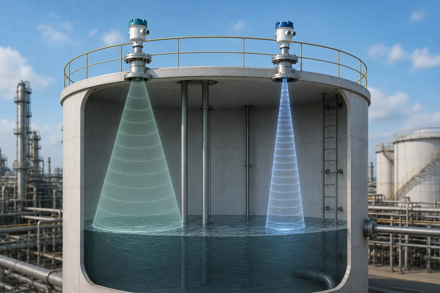
Neither 80 GHz radar nor ultrasonic measurement is universally better. Ultrasonic instruments can be suitable for straightforward applications with an adequate acoustic path. 80 GHz FMCW radar can offer advantages where a focused beam, compact antenna or electromagnetic measurement principle fits the vessel and medium. Selection should be based on the exact process, geometry, environment and verified model specifications.
For a broader overview of level measurement principles, applications and selection, see Level Measurement in Industrial Processes: Principles, Applications and Selection.
How ultrasonic measurement works
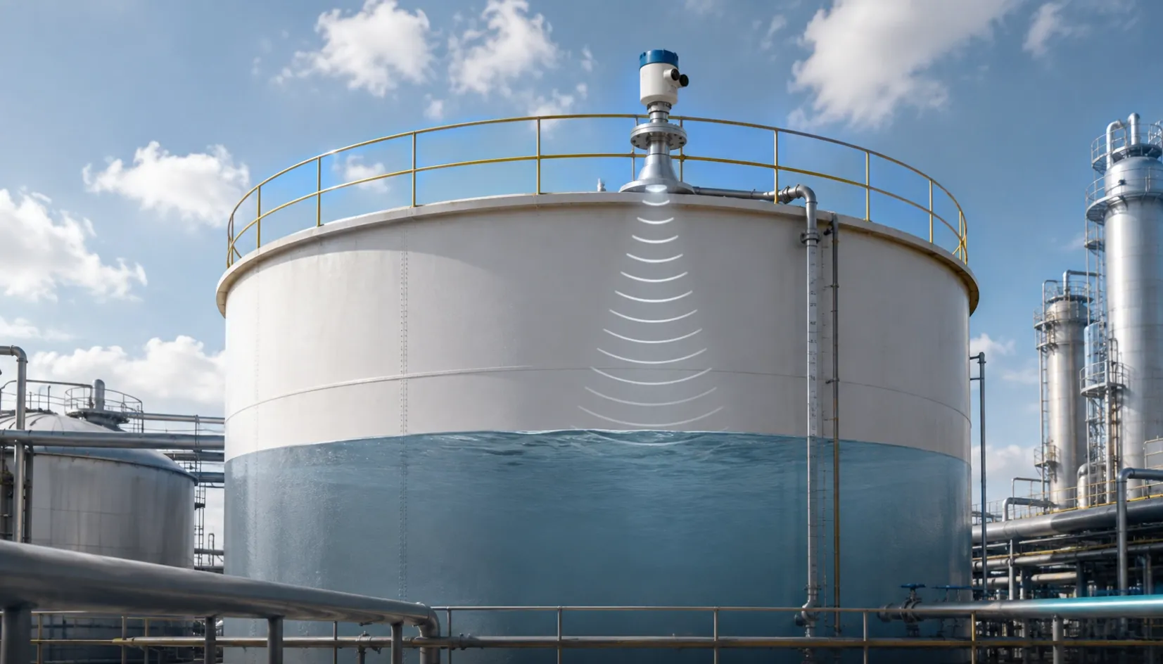
An ultrasonic instrument sends an acoustic pulse through the gas space and measures the return from the material surface. The instrument converts travel time into distance and then level.
Because the signal travels through the gas space, temperature gradients, gas composition, vapor, turbulence, foam and airborne material can influence propagation or echo quality. Process pressure may also affect application suitability depending on the instrument design and operating conditions. The significance depends on the application and the instrument’s design. Vessel geometry, mounting position and the target surface also matter.
Ultrasonic measurement can remain a practical option for open channels, water tanks and other applications where the acoustic path and environmental conditions are suitable. Model range, dead zone, beam pattern and compensation functions must be checked.
How 80 GHz FMCW radar works
FMCW radar transmits electromagnetic energy while varying frequency and evaluates the returned signal to determine distance. The 80 GHz frequency band can support a smaller antenna and a more focused beam than lower-frequency radar designs, depending on the instrument.
Radar is not automatically unaffected by every process condition. Antenna contamination, heavy buildup, condensation, foam, low reflectivity, vessel geometry, obstructions and installation position can still affect measurement. The selected antenna, process connection, signal processing and application limits should be reviewed.
Compare the installation
For either technology, document:
- vessel height and diameter;
- nozzle position and dimensions;
- internal ladders, pipes, agitators or supports;
- filling and discharge points;
- liquid or solid surface behavior;
- foam, vapor, dust, condensation or buildup;
- temperature and pressure conditions;
- required measuring range and dead zone;
- mounting access and maintenance conditions;
- output and control-system requirements.
A focused radar beam may help avoid some internal structures, but it does not remove the need for suitable mounting and echo review. Ultrasonic instruments also require a clear acoustic path and adequate separation from walls or obstructions.
Compare the measurement conditions
Vapor, temperature and gas-space conditions
Changes in the gas space can influence acoustic propagation. Radar uses electromagnetic waves, so it responds differently; however, the antenna and process environment still require evaluation.
Dust and airborne material
Airborne dust can affect signal propagation differently for ultrasonic and radar measurement. The effect depends on concentration, particle characteristics, signal path, instrument design and operating conditions. Representative process conditions should therefore be reviewed rather than relying on a general technology claim.
Foam and turbulent surfaces
Foam can reduce the quality of either acoustic or radar returns. Performance depends on foam properties, surface movement, signal frequency, installation and instrument processing.
Condensation and buildup
Condensation or buildup on the sensing surface may affect signal quality. Antenna or transducer design, orientation, cleaning and process connection should be considered.
Compare performance claims
Accuracy, range, beam angle, dead zone, environmental rating and temperature limits vary by model and configuration. Do not apply a value from one 80 GHz instrument to the entire technology, and do not assume every ultrasonic instrument has the same limitations.
The final result also depends on vessel geometry, installation, calibration and control-system scaling. Use the exact model documentation and application review as the selection basis.
Compare cost and maintenance
Initial price is only one factor. Installation work, commissioning, cleaning, access, false readings, process interruptions and replacement requirements may contribute to lifecycle cost. These costs are site-specific and cannot be predicted from the measurement principle alone.
Select the technology that meets the required measurement performance with an installation and maintenance plan the site can support. Avoid assuming that either technology always requires less maintenance or always produces a lower total cost.
Practical selection guide
Consider ultrasonic measurement when the acoustic path is suitable, the application is comparatively straightforward and its verified specifications meet the requirement.
Consider 80 GHz radar when a focused beam, compact mounting or radar principle is beneficial and the selected model has been reviewed for the medium, vessel and process conditions.
For difficult applications, provide vessel drawings, nozzle details, process conditions and photographs to the supplier. An application review or field test may be appropriate before finalizing the design.
Practical questions
Is 80 GHz radar an industry standard for every level application?
No. It is one available radar technology. Suitability depends on the measurement task, process, installation and model specifications.
Can radar always measure through steam, foam or condensation?
No. Radar responds differently from ultrasonic measurement, but heavy foam, condensation, buildup, geometry and target properties can still affect the signal.
Does a narrower beam guarantee correct measurement?
No. Beam focus can help with some vessel geometries, but mounting, obstructions, target properties, dead zone and signal processing remain important.
Which option has the lower lifecycle cost?
There is no universal answer. Compare purchase, installation, commissioning, access, cleaning, verification and process-impact costs for the actual site.
Next step
Prepare the vessel dimensions, nozzle details, medium, process conditions, expected level range and installation constraints. HRT can review available radar configurations and help compare them with other level-measurement options. Final suitability should be confirmed for the selected model and installation.
For applications where 80 GHz radar is being considered, see HRT-L280R 80 GHz Radar Level Transmitter for an available HRT radar configuration.
Contact our technical team with the operating conditions, installation details and required interface to request an application and configuration review.