Air Velocity Transmitters
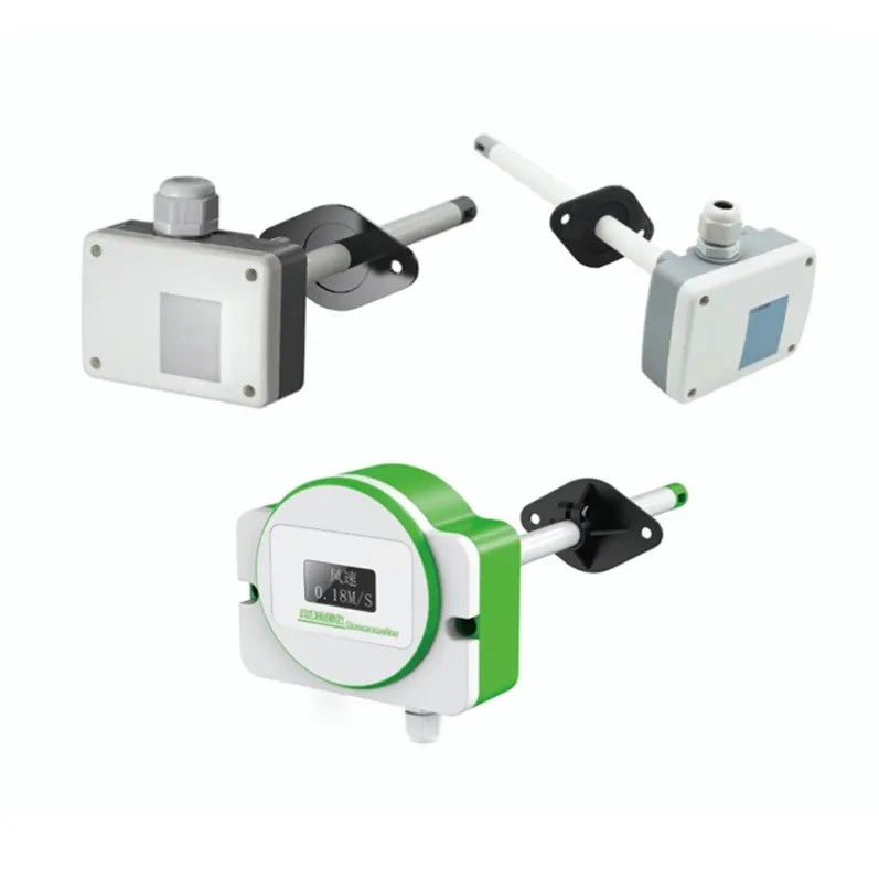
HRT-V180 Thermal Air Velocity Transmitter
Thermal air-velocity transmitter for duct, room or equipment airflow monitoring where the selected range and installation are suitable. Confirm expected velocity, direction, temperature, humidity, contamination, output and placement.
Specifications
- Product Type
- Thermal Anemometer / Air Velocity Transmitter
- Measuring Range
- 0-10, 0-20, 0-30, or 0-50 m/s (Selectable)
- Reference Accuracy
- <5 m/s: ±(5%rdg + 0.1m/s); >5 m/s: ±(3%rdg + 0.1m/s)
- Signal Output 1
- Analog: 4-20 mA / 0-5V / 0-10V
- Signal Output 2
- Digital: RS485 Modbus-RTU
- Response Time
- 200ms (Default); Supports 100ms High-speed
- Power Supply
- 12-24V DC
- Power Consumption
- ≤ 0.8W (Standard); ≤ 1.2W (With Display)
- Output Load
- Current: ≤ 500 Ω; Voltage: ≤ 2 MΩ
- Ingress Protection
- IP65 (Housing); IP00 (Sensing Probe)
- Operating Temp
- -10°C to +70°C
- Housing Material
- Flame-retardant material
- Airflow Calculation
- m³/h = Duct Area (m²) × Velocity (m/s) × 3600
- Customization
- Bespoke configurations available for specific duct, airflow and installation conditions
What this product is
Thermal air-velocity transmitter for duct, room or equipment airflow monitoring where the selected range and installation are suitable. Confirm expected velocity, direction, temperature, humidity, contamination, output and placement.
Application fit
This specialty measurement product can be reviewed when the process variable, fluid or airflow behavior, installation and required interface are defined with representative operating data.
Selection information required
- Expected measurement range and process-temperature range.
- Fluid or airflow behavior, direction, contamination and process geometry.
- Mounting or process connection, cleaning and maintenance requirements.
- Output, power, control objective and reference or verification method.
Installation and integration
Review the installation position, flow or process conditions, environmental exposure, cleaning method, wiring and access for inspection. Commissioning should compare the installed configuration with the approved application information.
Verified specifications
Use only specifications confirmed for the exact model and ordered configuration. Unverified numerical ranges, accuracy, materials, protection ratings, certifications, protocols and performance claims are intentionally not stated here.
Limitations and review conditions
Product names or family labels do not by themselves prove hazardous-area approval, waterproofing, corrosion resistance, hygienic suitability, wireless capability or compatibility with a particular medium or control system. Check the exact documentation and configuration before selection.
Next step
Contact our technical team with the medium, range, process conditions, connection, output and installation details to request a configuration review.